Vintage timer circuit rebuild
This project was a risky take for me, as I was not an expert in electrical, probably clueless and ignorant of the whole subject. During my university degree, I had a particularly unpleasant time studying electrical, saying by achieving less than 60% in all my undergrad electrical modules, while 80%+ in aero. However, karma is always on the corner if you choose to stick on the path of becoming an engineer. And, this has unfortunately cursed me a few weeks ago. The unlucky fact is that after two years of Cambridge undergraduate electrical training, I am an amateur in the subject, so I do feel the unpreventable need to write this blog and remind myself of the re-designing process, which might be useful in the future.
Where it all started
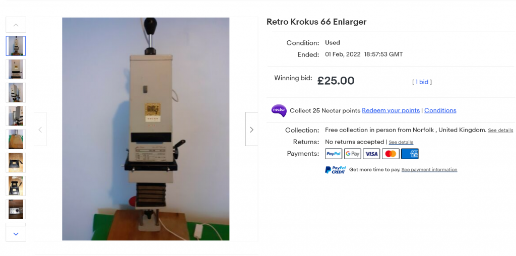
I came across a rather intriguing listing on eBay about a month ago: a reasonable £25 for a Polish-made Krokus 66 enlarger, with a ‘Jessops enlarger timer’ (note: foreshadowing here) complementarily sold. Back in that time, I thought the only drawback was it had to be collected in person, which is in Norfolk. I initially thought this wouldn’t be a long drive as it was just the next county across the pseudo-exclave town of Newmarket, totally forgetting the desperate journey to Wells-on-the-Sea…
I did regret after paying for the bid, which means a commitment to a 110 miles return journey to the lovely town of Harleston. After all, it turned out that the purchase and collection experience was not a disappointment. The seller kindly offer me a whole set of spare darkroom equipment for £15, which is definitely a bargain! Alas, I have a fully equipped darkroom, apart from a tin foil over the door window!
An ambitious masterplan
After returning home, I was unable to wait for the next day and start testing the equipment. Luckily, they all seemed to work seamlessly so far. I wasn’t expecting much from the enlarger, since it is basically an inverted camera with some lights and equipment for enlarging a 35 mm file. Furthermore, the timer seemed to work fine apart from some blown LEDs indicators.
The enlarger still uses an old and special opal 60 W incandescent bulb. Undoubtedly it was widely available back in the heydays of film photography. However, when things have all fallen under the shade of CMOS and the worthiest part of an enlarger has become its incredibly sharp lens, it would require a more difficult journey to acquire a replacement bulb of the same kind. Considering the availability, cost, and heat generation of the opal specialist incandescent bulb, I decided to use a LED bulb. After some research, see here, I have decided to use LED on my enlarger, based on the following justifications:
- I shoot in black and white, and monochromic photography should not be severely affected by the incomplete spectrum of a LED.
- It would be much easier to work with a 10 W LED than 100 W incandescent considering the amount of heat generated.
- The circuit should be able to handle novel bulb with no problem.
- This will save me a fortune on electricity bill and sourcing a identical replacement bulb
This was planned in two stages. I tested the system with a spare IKEA 4 W LED. It worked fine up to this stage and I tried to use the enlarger with my DSLR to digitise several negatives.
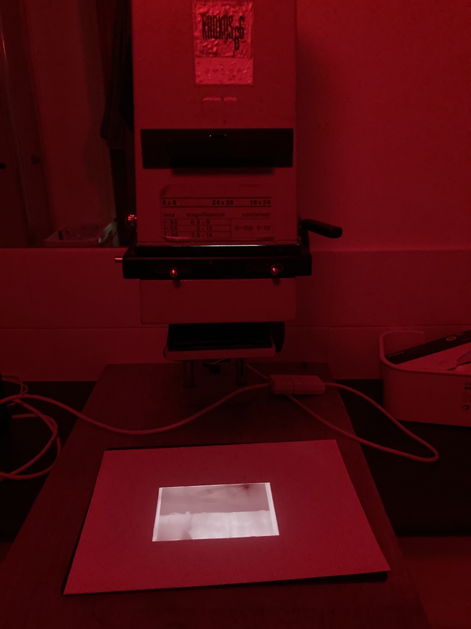
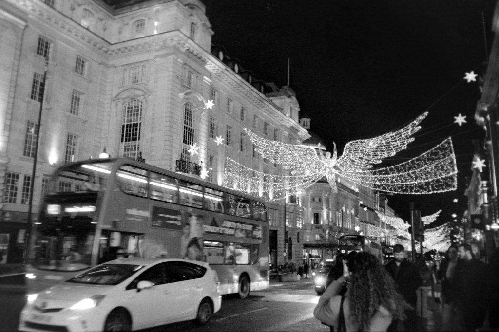
The digitised photo is at an acceptable standard. However, there are two main problems. 1 – The vignetting effect from the optical diffused was ignored at the setup and does cause the edge of pictures to have a mysterious glow (removed in postprocessing). Vignetting should theoretically be removable by carefully positioning the bulb. 2 – There is a significant amount of grain on the photo, which I suspect are due to the multiplication effect between the low-light 30 s DSLR exposure time and the grain on a 400-ISO film. This can only be solved by installing a more powerful bulb.
Replacing a bulb, which does not sound difficult.
How hard can it be?
Jeremy Clarkson
However, a hint you can tell from the title of this blog. It is neither about the digitalisation of film nor enlarger testing. It is about a timer circuit, which I have never mentioned until this point. After the good progress up to this point, I then happily purchased a 4000 K, 1531 lm Philips bulb from Amazon. Things started to screw up as soon as I screwed in this masterpiece of electronic inventions in the 21st century. The time is unable to switch off. It worked with an IKEA bulb, an OSRAM bulb, and even a Sainsbury’s bulb, but not Philips. I suspect some ingenious power-saving design has messed up the timer circuit, and quite possibly due to reactive power. Only until this point did I realise I never have heard a single click of a mechanical relay in the circuit, which means the circuit is probably using some cutting-edge semiconductor technology to control the circuit.
To investigate further on this error, I opened the controller and discovered it is a piece of excrement de boutique. This has nothing to do with Jessop neither. I have no idea which lunatic designed this circuit in 1988 but it is mind-blowingly ridiculous, even for someone in 2022.
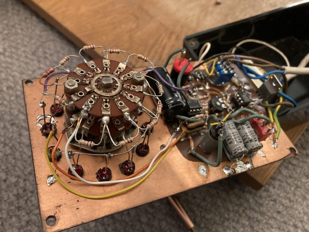
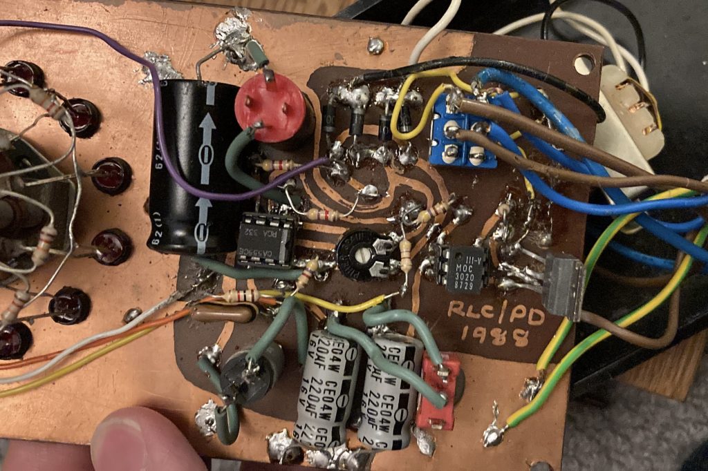
I immediately realised this was not a joke. Instead, a big project for me to finish.
to be continued…
Test results
I made a test on the finished circuit to check the illumination time of 1 – 3 s. As the currently-used step-down transformer does not supply constant voltage, I am paranoid about the stability of this circuit. The current trimmer resistor on pin 5 of the 7555 IC is 775 Ω / 5 kΩ.
| Set time [s] | Time [s] | Difference |
|---|---|---|
| 1 | 0.99 | -1.0% |
| 2 | 1.98 | -1.0% |
| 3 | 2.96 | -1.3% |
I would say this is good enough for my standard, considering the unstable step-down transformer. I would further tune the circuit when the new power supply has arrived.